Video Summary
This video demonstrates the configuration process of Tianjin Sentinel Electronic’s EtherNet/IP IO-Link master module with Inovance EVO521 PLC. The test system consists of an 8-port IO-Link master module, one 16-channel output M12 slave station, and one 16-channel input M12 slave station, connected to port 5 and port 6 of the master respectively.
Before configuration, the BUS indicator of the master module is solid red, and the RUN indicator of the slave modules is off, meaning communication between the master and PLC has not been established, nor has IO-Link communication. The video then shows downloading and installing DhcpTool from the official website, setting the master DIP switch to 0XFF for DHCP mode, and assigning an IP address.
After that, create a new project in Inovance programming software, install the ESI file of the master module, add an EtherNet/IP Scanner and the Sentinel master module, and set IO-LinkPort Config to 48 to enable ports 5 and 6 according to actual wiring.
Finally, download the program to the PLC and start running. After completion, the BUS indicator of the master turns solid green and the RUN indicators of the slaves turn solid green, indicating that both EtherNet/IP and IO-Link communications are successfully established.
Step-by-Step Configuration Guide
-
1. Set IP Address of Sentinel EtherNet/IP IO-Link Master Module
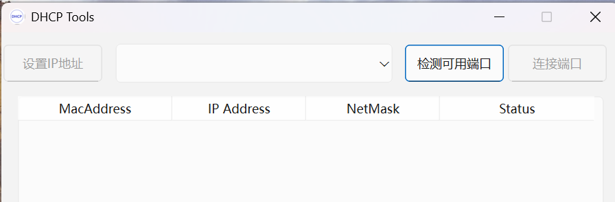
Method 1: Using Sentinel DhcpTool IP Configuration Software
- Download and install DhcpTool V1.2 from the Sentinel official website (Windows 10 or above only), then launch the software.
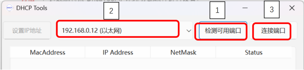
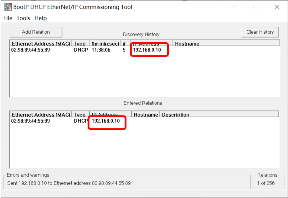
- Connect the Sentinel EtherNet/IP IO-Link master to your computer. Set the IP address DIP switches (ADDR_H to F, ADDR_L to F) to 0XFF (DHCP mode, waiting for IP assignment). Power-cycle the module; the BUS LED will flash red. Click Detect Available Ports → Connect Port.
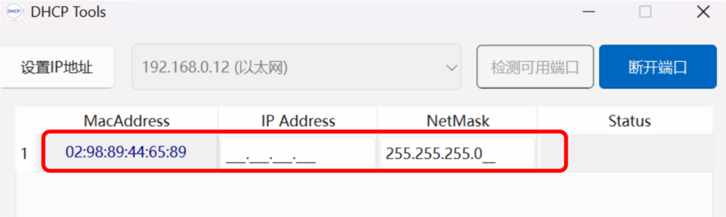
- The scanned Sentinel EtherNet/IP IO-Link master and its MAC address will appear below.
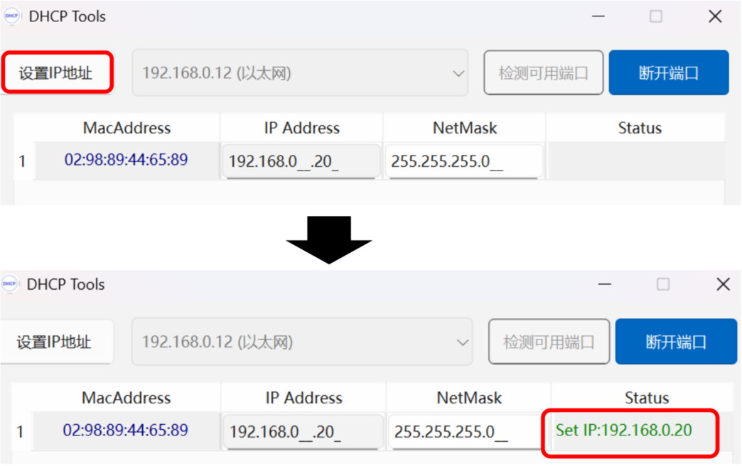
- Enter the desired IP address (e.g., 192.168.0.20) under IP Address and click Set IP Address. A green IP under Status means success. After setting, set switches to 0X00 to retain the IP on power cycle. Switches 0x01–0xFE use the DHCP subnet with the last octet defined by the switch value.
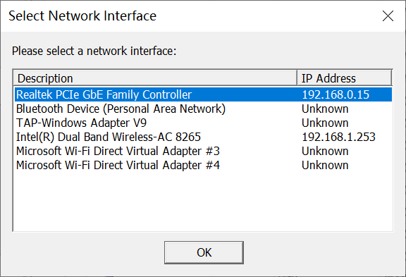
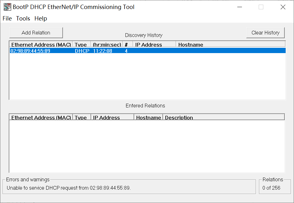
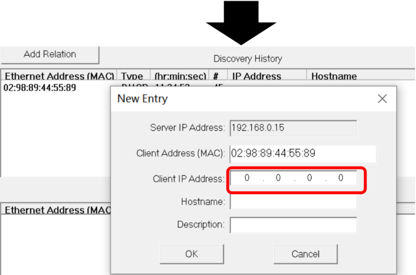
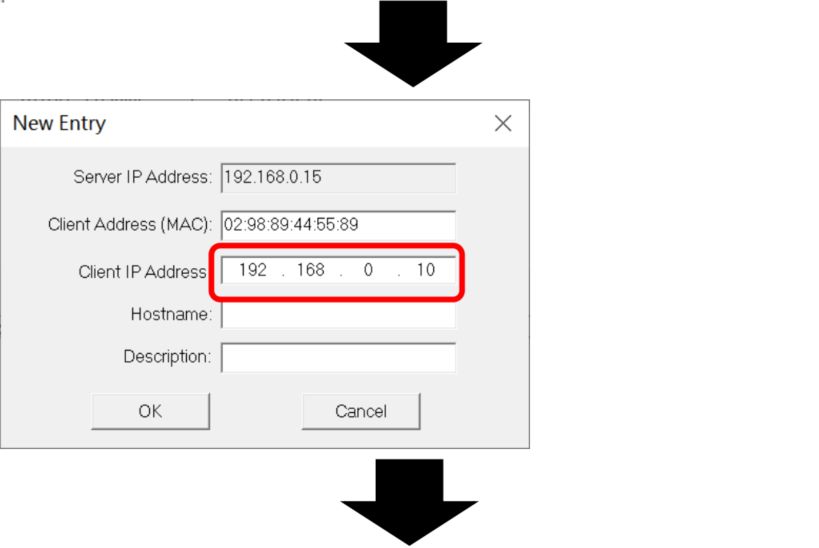
Method 2: Using Third-Party Software (AB Bootp-DHCP Tool)
- Set module switches to 0XFF (DHCP mode), power-cycle, and confirm the BUS LED flashes red. Open Bootp-DHCP Tool, select your network adapter, and click OK.
- Double-click the detected module, enter an IP in the same subnet as your PC, then click OK. After configuration, set switches to 0X00 for fixed IP operation.
-
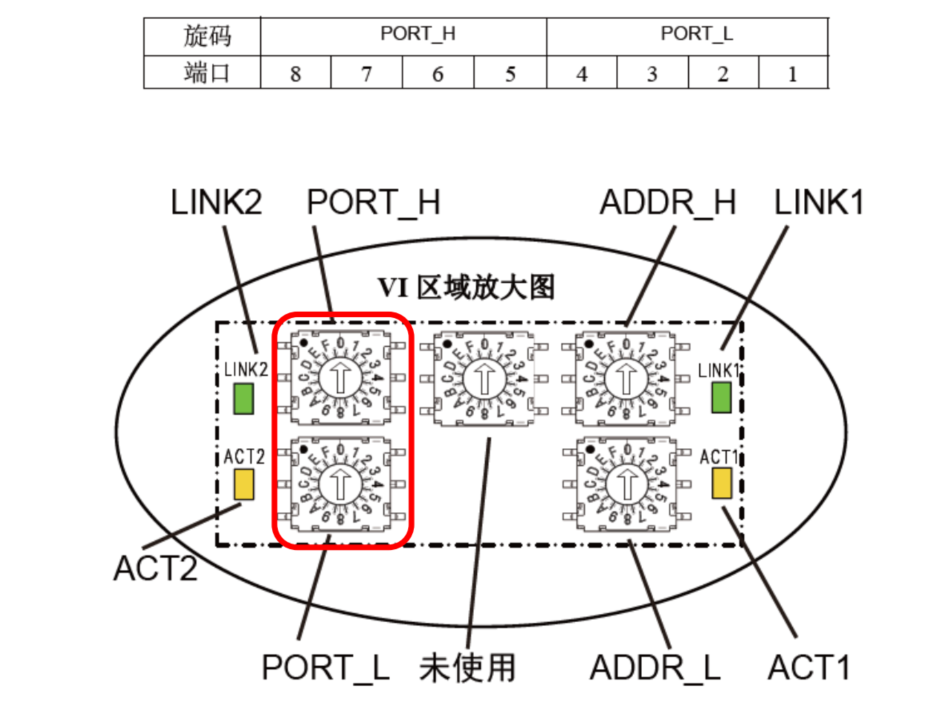
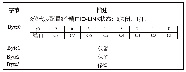
2. IO-Link Port Switch Settings
In this example, an 8-channel 4–20mA analog input slave (SIOL-M12-8AI) is connected to port 2 of the master. To enable IO-Link on port 2 only:
Binary: 00000010 → Hex: 0x02. Set PORT_H = 0, PORT_L = 2, then power-cycle the module.
-
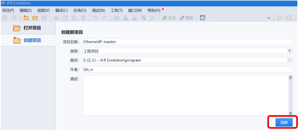
3. Open Inovance iFA Evolution and Create a New Project
-
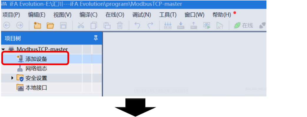
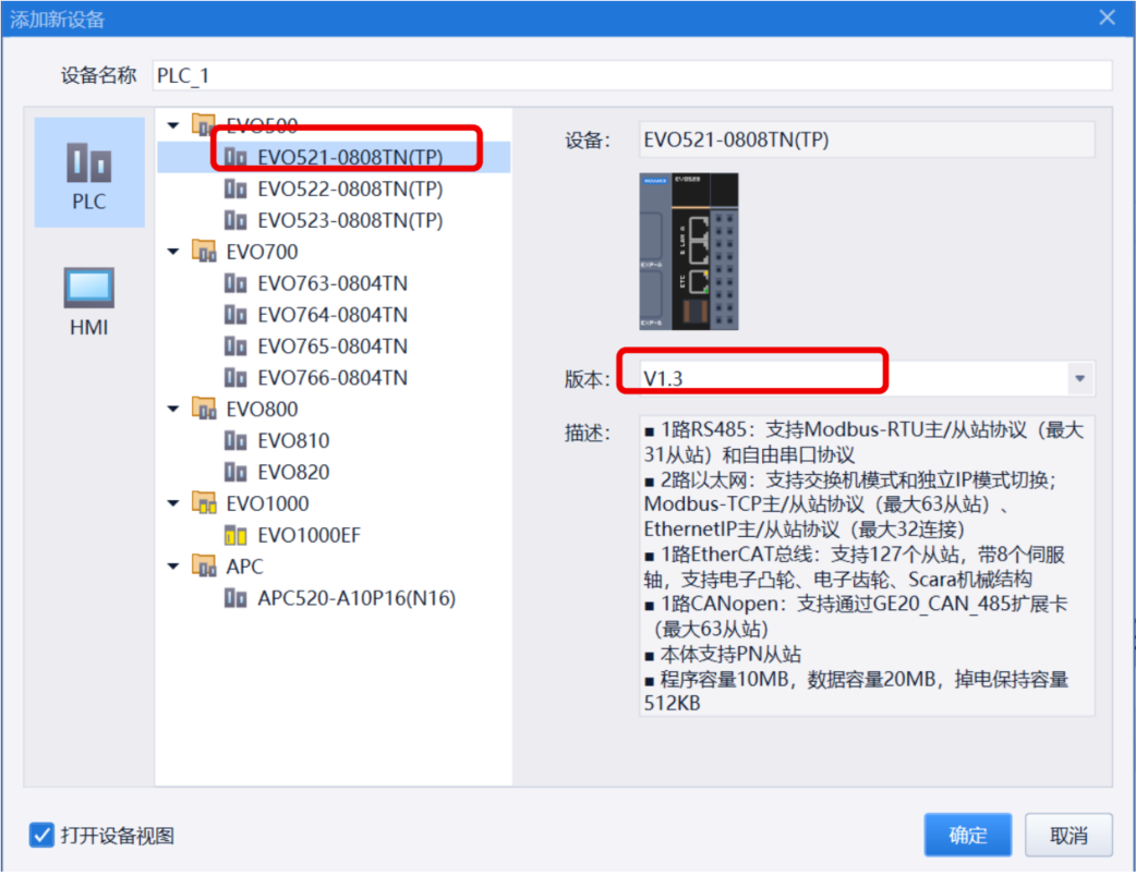
4. Add PLC Device (EVO521-0808 TP(TN) V1.3)
-
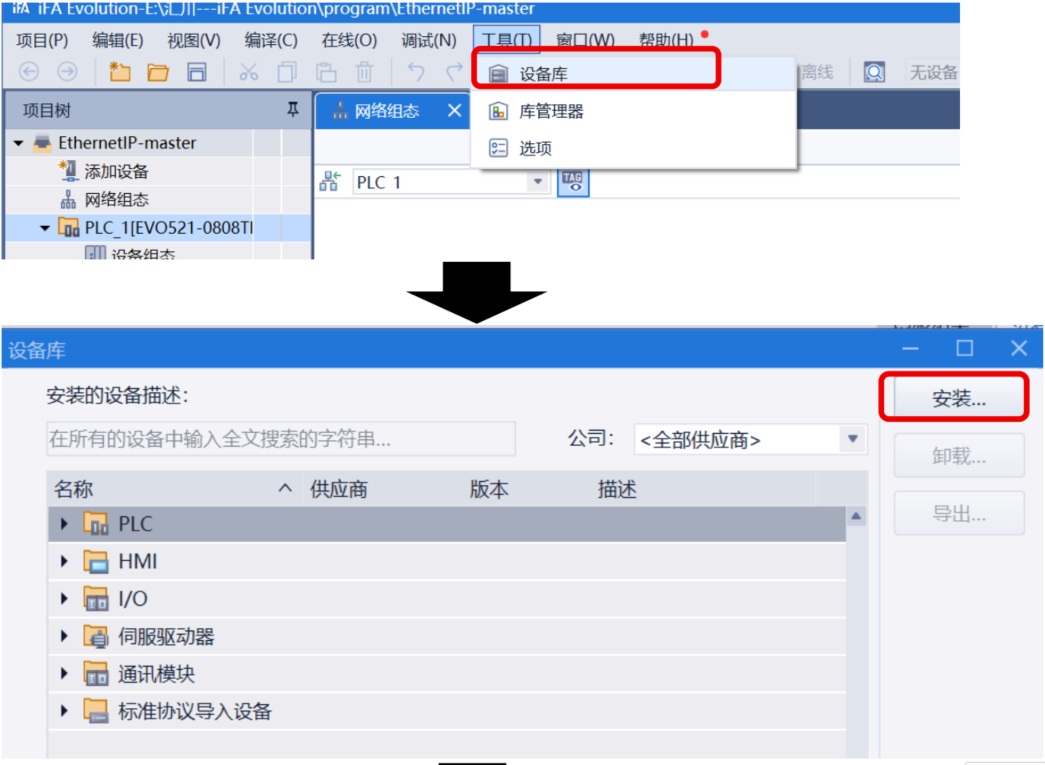
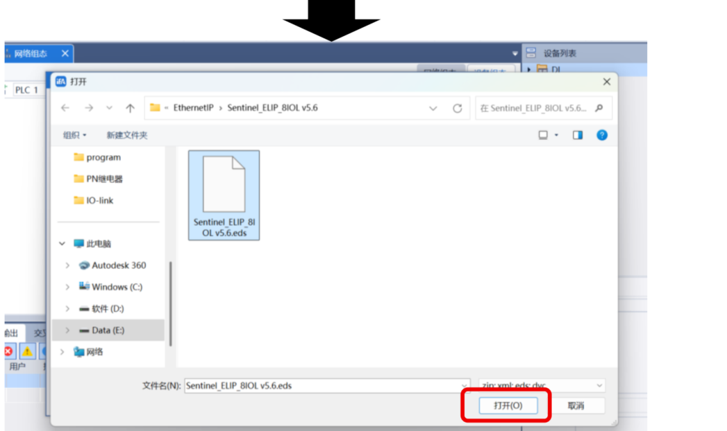
5. Install the ESI Device Description File
Go to Tools → Device Repository → Install, then select the ESI file path and open it.
-
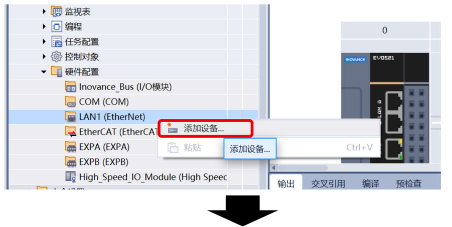
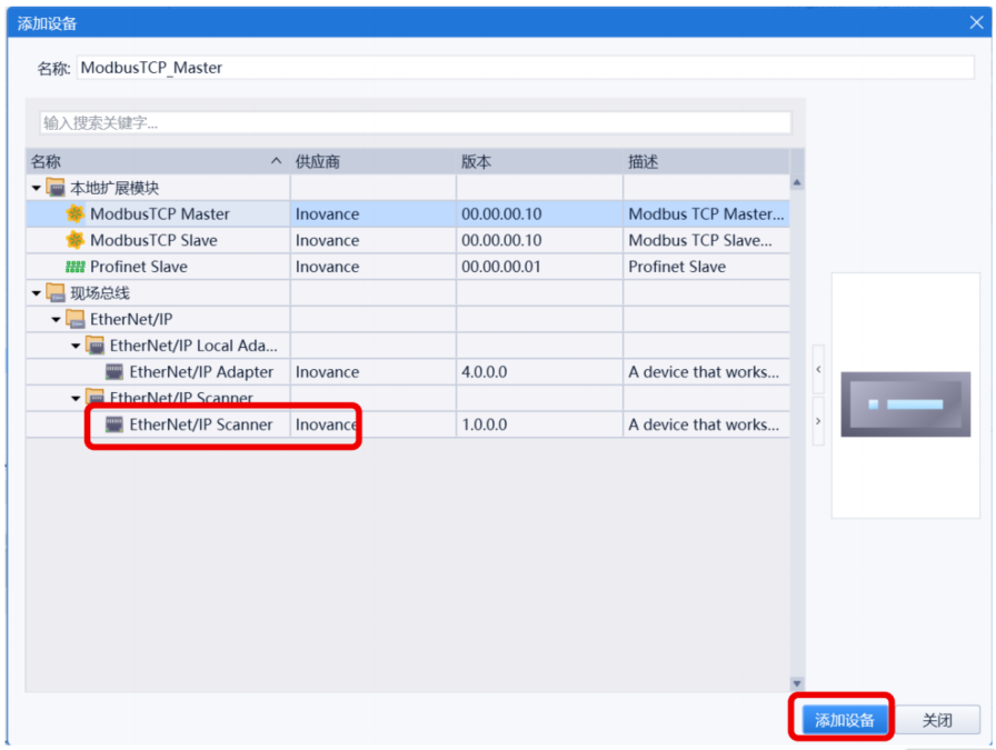
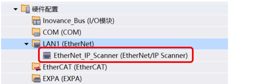
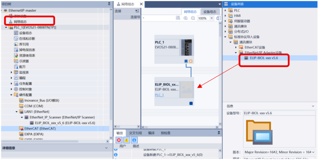
6. Add EtherNet/IP Scanner
Under Hardware Configuration → LAN1 (EtherNet), right-click and select Add Device → EtherNet/IP Scanner.
-
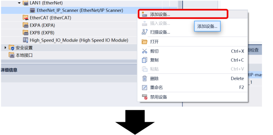
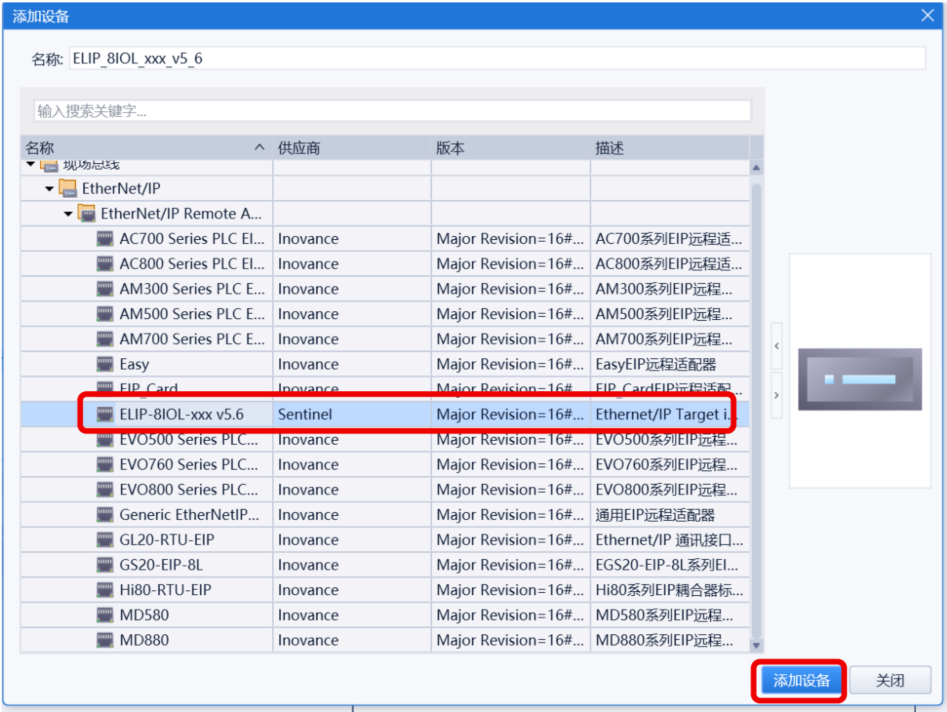
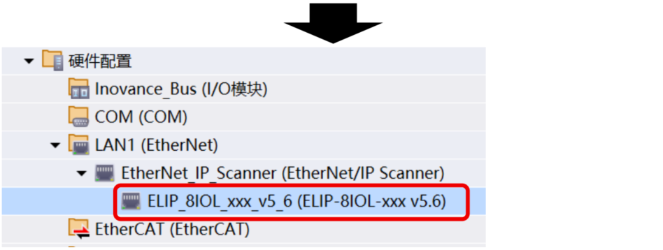
7. Add the Sentinel IO-Link Master Module
Method A: Right-click the Scanner → Add Device → select ELIP-8IOL-XXX V5.6.
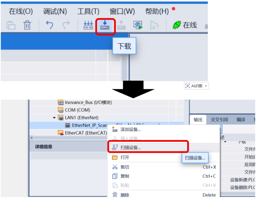
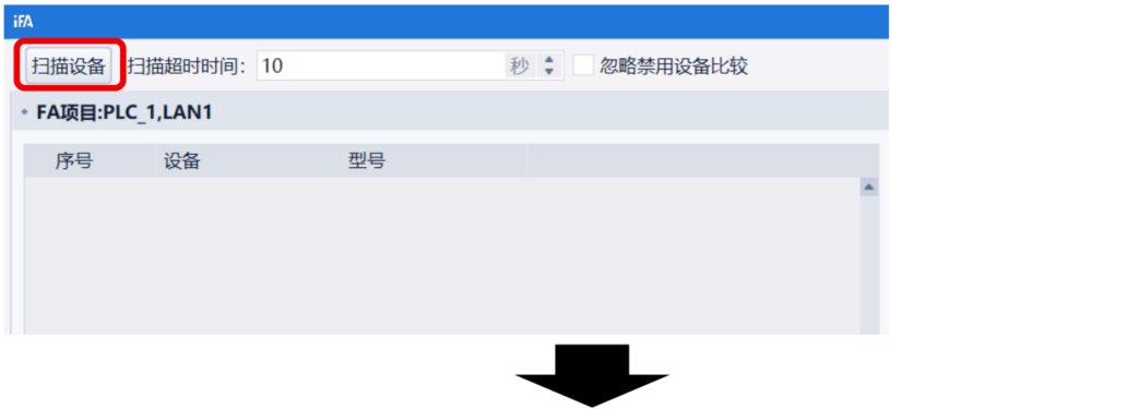
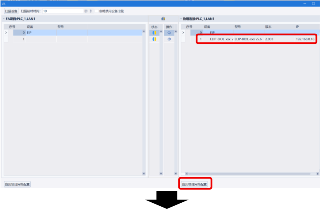
Method B: Download basic configuration first, then right-click Scanner → Scan Devices → Apply Physical Network Configuration.
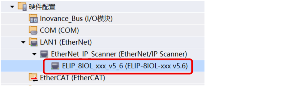
Method C: Open Network Configuration, drag ELIP-8IOL-XXX V5.6 from the device list and connect to LAN1.
-
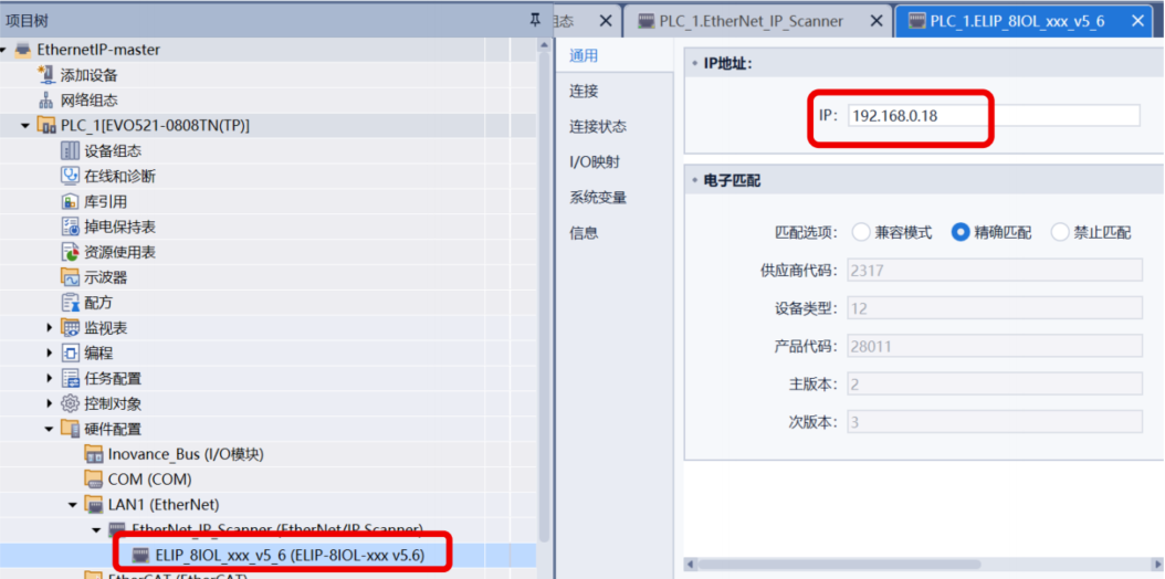
8. Set the Module IP Address
Double-click the module → go to General → enter the actual IP address of the module.
-
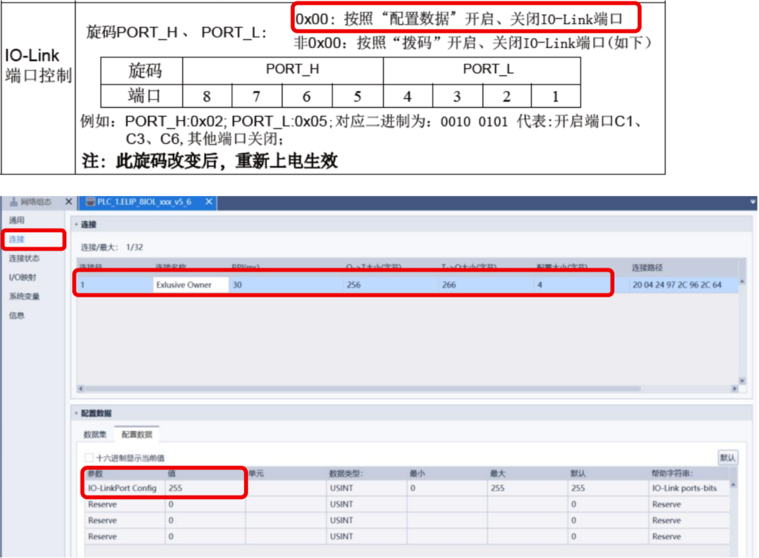
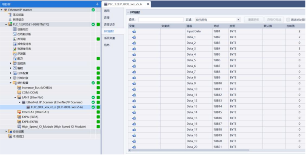
9. Configure IO-Link Port Parameters
On the Connection tab, default I/O sizes are Input: 266 bytes, Output: 256 bytes, Configuration: 4 bytes. The default IO-LinkPort Config = 255 (binary 11111111, all 8 ports enabled). To enable only specific ports, change this value and set the module IO-Link port control switch to 0X00.
-
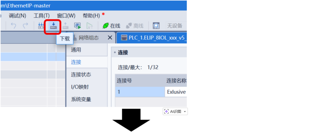
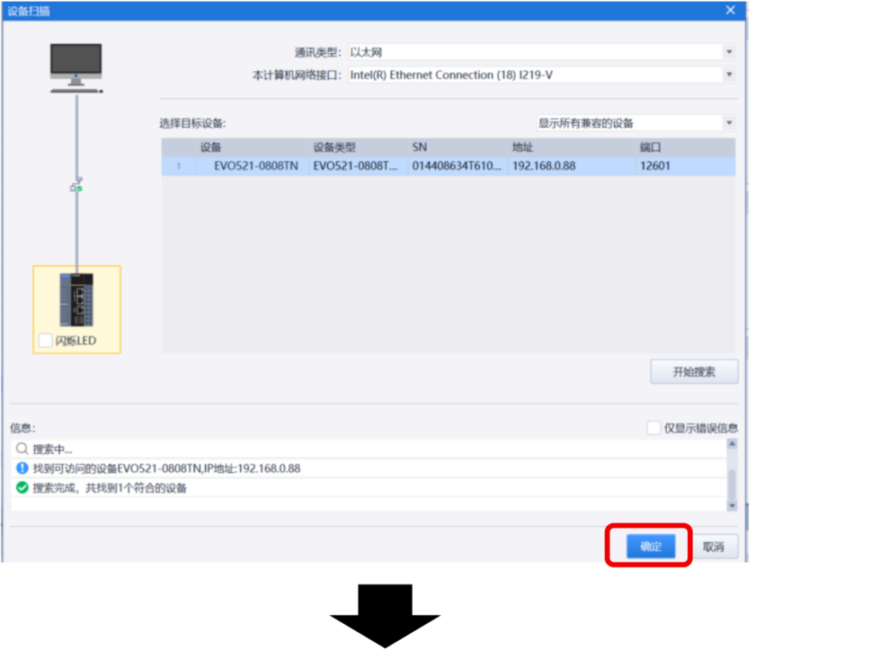
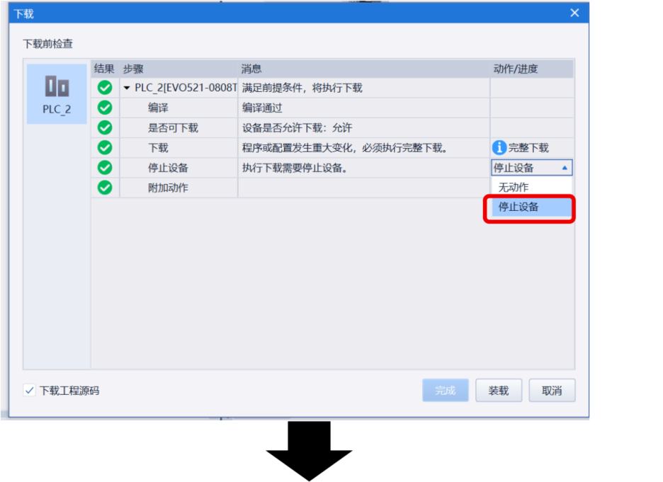
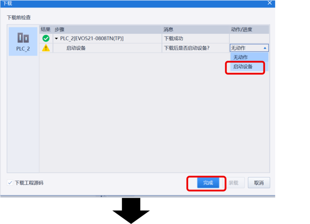
10. Download the Configuration to the PLC
-
11. Go Online for Monitoring
-
12. View I/O Mapping and Data Monitoring
The analog input slave on port 2 uses BYTE 42 to BYTE 57. The 4–20mA signal corresponds to a numerical range of 4000–20000, which can be monitored in real time in the I/O mapping area.
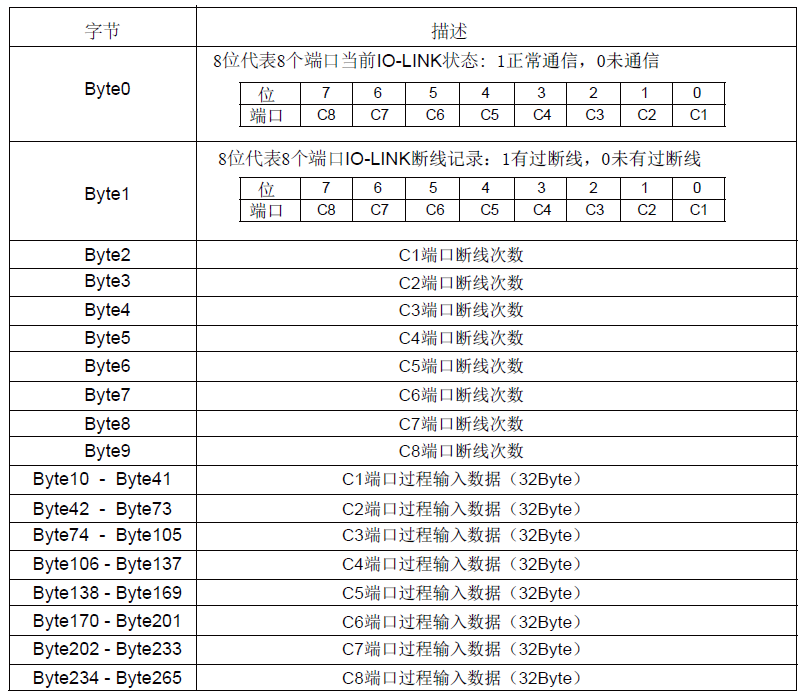
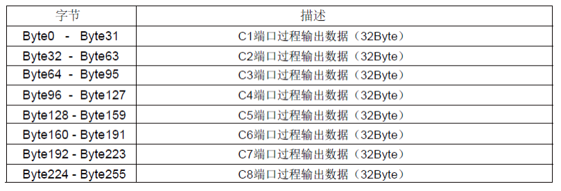
Appendix: Address Assignment Tables
Customer Support & Service
Tianjin Sentinel Electronic has over 17 years of experience in industrial automation, with more than 170 application cases in rail transit, automotive manufacturing, new energy, and other industries. We provide full lifecycle services from sensor selection and system integration to after-sales diagnosis.
Tel: +86 22-83726972
Website: www.sentinel-china.com
Welcome to schedule an online demo or request a trial unit. Our engineers will customize a complete solution from "data entry" to "action execution" for you.